 |
Open CASCADE Technology
7.4.0
|
|
 |
Open CASCADE Technology
7.4.0
|
|
This tutorial will teach you how to use Open CASCADE Technology services to model a 3D object. The purpose of this tutorial is not to describe all Open CASCADE Technology classes but to help you start thinking in terms of Open CASCADE Technology as a tool.
This tutorial assumes that you have experience in using and setting up C++. From a programming standpoint, Open CASCADE Technology is designed to enhance your C++ tools with 3D modeling classes, methods and functions. The combination of all these resources will allow you to create substantial applications.
To illustrate the use of classes provided in the 3D geometric modeling toolkits, you will create a bottle as shown:
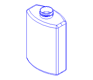
In the tutorial we will create, step-by-step, a function that will model a bottle as shown above. You will find the complete source code of this tutorial, including the very function MakeBottle in the distribution of Open CASCADE Technology. The function body is provided in the file samples/qt/Tutorial/src/MakeBottle.cxx.
We first define the bottle specifications as follows:
| Object Parameter | Parameter Name | Parameter Value |
|---|---|---|
| Bottle height | MyHeight | 70mm |
| Bottle width | MyWidth | 50mm |
| Bottle thickness | MyThickness | 30mm |
In addition, we decide that the bottle's profile (base) will be centered on the origin of the global Cartesian coordinate system.
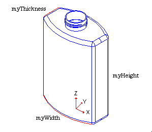
This modeling requires four steps:
To create the bottle's profile, you first create characteristic points with their coordinates as shown below in the (XOY) plane. These points will be the supports that define the geometry of the profile.
There are two classes to describe a 3D Cartesian point from its X, Y and Z coordinates in Open CASCADE Technology:
A handle is a type of smart pointer that provides automatic memory management. To choose the best class for this application, consider the following:
Since all the points you will define are only used to create the profile's curves, an object with a limited lifetime will do. Choose the gp_Pnt class. To instantiate a gp_Pnt object, just specify the X, Y, and Z coordinates of the points in the global Cartesian coordinate system:
Once your objects are instantiated, you can use methods provided by the class to access and modify its data. For example, to get the X coordinate of a point:
With the help of the previously defined points, you can compute a part of the bottle's profile geometry. As shown in the figure below, it will consist of two segments and one arc.

To create such entities, you need a specific data structure, which implements 3D geometric objects. This can be found in the Geom package of Open CASCADE Technology. In Open CASCADE Technology a package is a group of classes providing related functionality. The classes have names that start with the name of a package they belong to. For example, Geom_Line and Geom_Circle classes belong to the Geom package. The Geom package implements 3D geometric objects: elementary curves and surfaces are provided as well as more complex ones (such as Bezier and BSpline). However, the Geom package provides only the data structure of geometric entities. You can directly instantiate classes belonging to Geom, but it is easier to compute elementary curves and surfaces by using the GC package. This is because the GC provides two algorithm classes which are exactly what is required for our profile:
Both of these classes return a Geom_TrimmedCurve manipulated by handle. This entity represents a base curve (line or circle, in our case), limited between two of its parameter values. For example, circle C is parameterized between 0 and 2PI. If you need to create a quarter of a circle, you create a Geom_TrimmedCurve on C limited between 0 and M_PI/2.
All GC classes provide a casting method to obtain a result automatically with a function-like call. Note that this method will raise an exception if construction has failed. To handle possible errors more explicitly, you may use the IsDone and Value methods. For example:
You have created the support geometry of one part of the profile but these curves are independent with no relations between each other. To simplify the modeling, it would be right to manipulate these three curves as a single entity. This can be done by using the topological data structure of Open CASCADE Technology defined in the TopoDS package: it defines relationships between geometric entities which can be linked together to represent complex shapes. Each object of the TopoDS package, inheriting from the TopoDS_Shape class, describes a topological shape as described below:
| Shape | Open CASCADE Technology Class | Description |
|---|---|---|
| Vertex | TopoDS_Vertex | Zero dimensional shape corresponding to a point in geometry. |
| Edge | TopoDS_Edge | One-dimensional shape corresponding to a curve and bounded by a vertex at each extremity. |
| Wire | TopoDS_Wire | Sequence of edges connected by vertices. |
| Face | TopoDS_Face | Part of a surface bounded by a closed wire(s). |
| Shell | TopoDS_Shell | Set of faces connected by edges. |
| Solid | TopoDS_Solid | Part of 3D space bounded by Shells. |
| CompSolid | TopoDS_CompSolid | Set of solids connected by their faces. |
| Compound | TopoDS_Compound | Set of any other shapes described above. |
Referring to the previous table, to build the profile, you will create:

However, the TopoDS package provides only the data structure of the topological entities. Algorithm classes available to compute standard topological objects can be found in the BRepBuilderAPI package. To create an edge, you use the BRepBuilderAPI_MakeEdge class with the previously computed curves:
In Open CASCADE Technology, you can create edges in several ways. One possibility is to create an edge directly from two points, in which case the underlying geometry of this edge is a line, bounded by two vertices being automatically computed from the two input points. For example, aEdge1 and aEdge3 could have been computed in a simpler way:
To connect the edges, you need to create a wire with the BRepBuilderAPI_MakeWire class. There are two ways of building a wire with this class:
When building a wire from less than four edges, as in the present case, you can use the constructor directly as follows:
Once the first part of your wire is created you need to compute the complete profile. A simple way to do this is to:
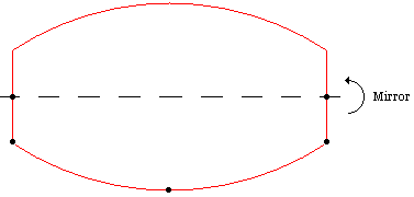
To apply a transformation on shapes (including wires), you first need to define the properties of a 3D geometric transformation by using the gp_Trsf class. This transformation can be a translation, a rotation, a scale, a reflection, or a combination of these. In our case, we need to define a reflection with respect to the X axis of the global coordinate system. An axis, defined with the gp_Ax1 class, is built out of a point and has a direction (3D unitary vector). There are two ways to define this axis. The first way is to define it from scratch, using its geometric definition:
The second and simplest way is to use the geometric constants defined in the gp package (origin, main directions and axis of the global coordinate system). To get the X axis, just call the gp::OX method:
As previously explained, the 3D geometric transformation is defined with the gp_Trsf class. There are two different ways to use this class:
Since the simplest approach is always the best one, you should use the SetMirror method with the axis as the center of symmetry.
You now have all necessary data to apply the transformation with the BRepBuilderAPI_Transform class by specifying:
BRepBuilderAPI_Transform does not modify the nature of the shape: the result of the reflected wire remains a wire. But the function-like call or the BRepBuilderAPI_Transform::Shape method returns a TopoDS_Shape object:
What you need is a method to consider the resulting reflected shape as a wire. The TopoDS global functions provide this kind of service by casting a shape into its real type. To cast the transformed wire, use the TopoDS::Wire method.
The bottle's profile is almost finished. You have created two wires: aWire and aMirroredWire. You need to concatenate them to compute a single shape. To do this, you use the BRepBuilderAPI_MakeWire class as follows:
To compute the main body of the bottle, you need to create a solid shape. The simplest way is to use the previously created profile and to sweep it along a direction. The Prism functionality of Open CASCADE Technology is the most appropriate for that task. It accepts a shape and a direction as input and generates a new shape according to the following rules:
| Shape | Generates |
|---|---|
| Vertex | Edge |
| Edge | Face |
| Wire | Shell |
| Face | Solid |
| Shell | Compound of Solids |
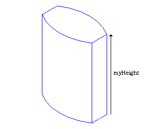
Your current profile is a wire. Referring to the Shape/Generates table, you need to compute a face out of its wire to generate a solid. To create a face, use the BRepBuilderAPI_MakeFace class. As previously explained, a face is a part of a surface bounded by a closed wire. Generally, BRepBuilderAPI_MakeFace computes a face out of a surface and one or more wires. When the wire lies on a plane, the surface is automatically computed.
The BRepPrimAPI package provides all the classes to create topological primitive constructions: boxes, cones, cylinders, spheres, etc. Among them is the BRepPrimAPI_MakePrism class. As specified above, the prism is defined by:
You want the solid to be finite, swept along the Z axis and to be myHeight height. The vector, defined with the gp_Vec class on its X, Y and Z coordinates, is:
All the necessary data to create the main body of your bottle is now available. Just apply the BRepPrimAPI_MakePrism class to compute the solid:
The edges of the bottle's body are very sharp. To replace them by rounded faces, you use the Fillet functionality of Open CASCADE Technology. For our purposes, we will specify that fillets must be:
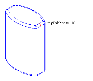
To apply fillets on the edges of a shape, you use the BRepFilletAPI_MakeFillet class. This class is normally used as follows:
To add the fillet description, you need to know the edges belonging to your shape. The best solution is to explore your solid to retrieve its edges. This kind of functionality is provided with the TopExp_Explorer class, which explores the data structure described in a TopoDS_Shape and extracts the sub-shapes you specifically need. Generally, this explorer is created by providing the following information:
An explorer is usually applied in a loop by using its three main methods:
In the explorer loop, you have found all the edges of the bottle shape. Each one must then be added in the BRepFilletAPI_MakeFillet instance with the Add() method. Do not forget to specify the radius of the fillet along with it.
Once this is done, you perform the last step of the procedure by asking for the filleted shape.
To add a neck to the bottle, you will create a cylinder and fuse it to the body. The cylinder is to be positioned on the top face of the body with a radius of myThickness / 4. and a height of myHeight / 10.
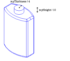
To position the cylinder, you need to define a coordinate system with the gp_Ax2 class defining a right-handed coordinate system from a point and two directions - the main (Z) axis direction and the X direction (the Y direction is computed from these two). To align the neck with the center of the top face, being in the global coordinate system (0, 0, myHeight), with its normal on the global Z axis, your local coordinate system can be defined as follows:
To create a cylinder, use another class from the primitives construction package: the BRepPrimAPI_MakeCylinder class. The information you must provide is:
You now have two separate parts: a main body and a neck that you need to fuse together. The BRepAlgoAPI package provides services to perform Boolean operations between shapes, and especially: common (Boolean intersection), cut (Boolean subtraction) and fuse (Boolean union). Use BRepAlgoAPI_Fuse to fuse the two shapes:
Since a real bottle is used to contain liquid material, you should now create a hollowed solid from the bottle's top face. In Open CASCADE Technology, a hollowed solid is called a Thick Solid and is internally computed as follows:
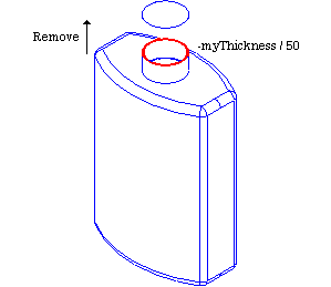
To compute a thick solid, you create an instance of the BRepOffsetAPI_MakeThickSolid class by giving the following information:
The challenging part in this procedure is to find the face to remove from your shape - the top face of the neck, which:
To find the face with such characteristics, you will once again use an explorer to iterate on all the bottle's faces to find the appropriate one.
For each detected face, you need to access the geometric properties of the shape: use the BRep_Tool class for that. The most commonly used methods of this class are:
As you can see, the BRep_Tool::Surface method returns an instance of the Geom_Surface class manipulated by handle. However, the Geom_Surface class does not provide information about the real type of the object aSurface, which could be an instance of Geom_Plane, Geom_CylindricalSurface, etc. All objects manipulated by handle, like Geom_Surface, inherit from the Standard_Transient class which provides two very useful methods concerning types:
DynamicType returns the real type of the object, but you need to compare it with the existing known types to determine whether aSurface is a plane, a cylindrical surface or some other type. To compare a given type with the type you seek, use the STANDARD_TYPE macro, which returns the type of a class:
If this comparison is true, you know that the aSurface real type is Geom_Plane. You can then convert it from Geom_Surface to Geom_Plane by using the DownCast() method provided by each class inheriting Standard_Transient. As its name implies, this static method is used to downcast objects to a given type with the following syntax:
Remember that the goal of all these conversions is to find the highest face of the bottle lying on a plane. Suppose that you have these two global variables:
You can easily find the plane whose origin is the biggest in Z knowing that the location of the plane is given with the Geom_Plane::Location method. For example:
You have now found the top face of the neck. Your final step before creating the hollowed solid is to put this face in a list. Since more than one face can be removed from the initial solid, the BRepOffsetAPI_MakeThickSolid constructor takes a list of faces as arguments. Open CASCADE Technology provides many collections for different kinds of objects: see TColGeom package for collections of objects from Geom package, TColgp package for collections of objects from gp package, etc. The collection for shapes can be found in the TopTools package. As BRepOffsetAPI_MakeThickSolid requires a list, use the TopTools_ListOfShape class.
All the necessary data are now available so you can create your hollowed solid by calling the BRepOffsetAPI_MakeThickSolid MakeThickSolidByJoin method:
Up to now, you have learned how to create edges out of 3D curves. You will now learn how to create an edge out of a 2D curve and a surface. To learn this aspect of Open CASCADE Technology, you will build helicoidal profiles out of 2D curves on cylindrical surfaces. The theory is more complex than in previous steps, but applying it is very simple. As a first step, you compute these cylindrical surfaces. You are already familiar with curves of the Geom package. Now you can create a cylindrical surface (Geom_CylindricalSurface) using:
Using the same coordinate system neckAx2 used to position the neck, you create two cylindrical surfaces Geom_CylindricalSurface with the following radii:
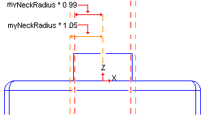
Notice that one of the cylindrical surfaces is smaller than the neck. There is a good reason for this: after the thread creation, you will fuse it with the neck. So, we must make sure that the two shapes remain in contact.
To create the neck of the bottle, you made a solid cylinder based on a cylindrical surface. You will create the profile of threading by creating 2D curves on such a surface. All geometries defined in the Geom package are parameterized. This means that each curve or surface from Geom is computed with a parametric equation. A Geom_CylindricalSurface surface is defined with the following parametric equation:
P(U, V) = O + R * (cos(U) * xDir + sin(U) * yDir) + V * zDir, where :

The advantage of having such parameterized geometries is that you can compute, for any (U, V) parameters of the surface:
There is another advantage of these parametric equations: you can consider a surface as a 2D parametric space defined with a (U, V) coordinate system. For example, consider the parametric ranges of the neck's surface:
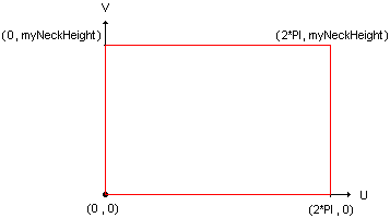
Suppose that you create a 2D line on this parametric (U, V) space and compute its 3D parametric curve. Depending on the line definition, results are as follows:
| Case | Parametric Equation | Parametric Curve |
|---|---|---|
| U = 0 | P(V) = O + V * zDir | Line parallel to the Z direction |
| V = 0 | P(U) = O + R * (cos(U) * xDir + sin(U) * yDir) | Circle parallel to the (O, X, Y) plane |
| U != 0 V != 0 | P(U, V) = O + R * (cos(U) * xDir + sin(U) * yDir) + V * zDir | Helicoidal curve describing the evolution of height and angle on the cylinder |
The helicoidal curve type is exactly what you need. On the neck's surface, the evolution laws of this curve will be:
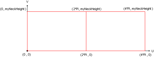
In this (U, V) parametric space, you will create a local (X, Y) coordinate system to position the curves to be created. This coordinate system will be defined with:
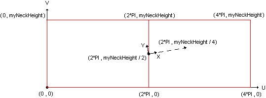
To use 2D primitive geometry types of Open CASCADE Technology for defining a point and a coordinate system, you will once again instantiate classes from gp:
You will now define the curves. As previously mentioned, these thread profiles are computed on two cylindrical surfaces. In the following figure, curves on the left define the base (on aCyl1 surface) and the curves on the right define the top of the thread's shape (on aCyl2 surface).

You have already used the Geom package to define 3D geometric entities. For 2D, you will use the Geom2d package. As for Geom, all geometries are parameterized. For example, a Geom2d_Ellipse ellipse is defined from:
Supposing that:
Your ellipses are defined as follows:
To describe portions of curves for the arcs drawn above, you define Geom2d_TrimmedCurve trimmed curves out of the created ellipses and two parameters to limit them. As the parametric equation of an ellipse is P(U) = O + (MajorRadius * cos(U) * XDirection) + (MinorRadius * sin(U) * YDirection), the ellipses need to be limited between 0 and M_PI.
The last step consists in defining the segment, which is the same for the two profiles: a line limited by the first and the last point of one of the arcs. To access the point corresponding to the parameter of a curve or a surface, you use the Value or D0 method (meaning 0th derivative), D1 method is for first derivative, D2 for the second one.
When creating the bottle's profile, you used classes from the GC package, providing algorithms to create elementary geometries. In 2D geometry, this kind of algorithms is found in the GCE2d package. Class names and behaviors are similar to those in GC. For example, to create a 2D segment out of two points:
As you did when creating the base profile of the bottle, you can now:

Previously, you have built:
To compute the edges out of these curves, once again use the BRepBuilderAPI_MakeEdge class. One of its constructors allows you to build an edge out of a curve described in the 2D parametric space of a surface.
Now, you can create the two profiles of the threading, lying on each surface.
Remember that these wires were built out of a surface and 2D curves. One important data item is missing as far as these wires are concerned: there is no information on the 3D curves. Fortunately, you do not need to compute this yourself, which can be a difficult task since the mathematics can be quite complex. When a shape contains all the necessary information except 3D curves, Open CASCADE Technology provides a tool to build them automatically. In the BRepLib tool package, you can use the BuildCurves3d method to compute 3D curves for all the edges of a shape.
You have computed the wires of the threading. The threading will be a solid shape, so you must now compute the faces of the wires, the faces allowing you to join the wires, the shell out of these faces and then the solid itself. This can be a lengthy operation. There are always faster ways to build a solid when the base topology is defined. You would like to create a solid out of two wires. Open CASCADE Technology provides a quick way to do this by building a loft: a shell or a solid passing through a set of wires in a given sequence. The loft function is implemented in the BRepOffsetAPI_ThruSections class, which you use as follows:
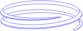
You are almost done building the bottle. Use the TopoDS_Compound and BRep_Builder classes to build single shape from myBody and myThreading:
Congratulations! Your bottle is complete. Here is the result snapshot of the Tutorial application:
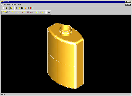
We hope that this tutorial has provided you with a feel for the industrial strength power of Open CASCADE Technology. If you want to know more and develop major projects using Open CASCADE Technology, we invite you to study our training, support, and consulting services on our site at https://www.opencascade.com/content/technology-support. Our professional services can maximize the power of your Open CASCADE Technology applications.
Complete definition of MakeBottle function (defined in the file src/MakeBottle.cxx of the Tutorial):