|
Open CASCADE Technology
7.4.0
|
|
|
Open CASCADE Technology
7.4.0
|
|
This document provides OCCT developers and contributors with an overview and practical guidelines for work with OCCT automatic testing system.
Reading the Introduction should be sufficient for developers to use the test system to control non-regression of the modifications they implement in OCCT. Other sections provide a more in-depth description of the test system, required for modifying the tests and adding new test cases.
OCCT automatic testing system is organized around DRAW Test Harness, a console application based on Tcl (a scripting language) interpreter extended by OCCT-related commands.
Standard OCCT tests are included with OCCT sources and are located in subdirectory tests of the OCCT root folder. Other test folders can be included in the test system, e.g. for testing applications based on OCCT.
The tests are organized in three levels:
See Test Groups chapter for the current list of available test groups and grids.
Each modification made in OCCT code must be checked for non-regression by running the whole set of tests. The developer who makes the modification is responsible for running and ensuring non-regression for the tests available to him.
Note that many tests are based on data files that are confidential and thus available only at OPEN CASCADE. The official certification testing of each change before its integration to master branch of official OCCT Git repository (and finally to the official release) is performed by OPEN CASCADE to ensure non-regression on all existing test cases and supported platforms.
Each new non-trivial modification (improvement, bug fix, new feature) in OCCT should be accompanied by a relevant test case suitable for verifying that modification. This test case is to be added by the developer who provides the modification.
If a modification affects the result of an existing test case, either the modification should be corrected (if it causes regression) or the affected test cases should be updated to account for the modification.
The modifications made in the OCCT code and related test scripts should be included in the same integration to the master branch.
Before running tests, make sure to define environment variable CSF_TestDataPath pointing to the directory containing test data files.
For this it is recommended to add a file DrawAppliInit in the directory which is current at the moment of starting DRAWEXE (normally it is OCCT root directory, $CASROOT ). This file is evaluated automatically at the DRAW start.
Example (Windows)
Note that variable CSF_TestDataPath is set to default value at DRAW start, pointing at the folder $CASROOT/data. In this example, subdirectory d:/occt/test-data is added to this path. Similar code could be used on Linux and Mac OS X except that on non-Windows platforms colon ":" should be used as path separator instead of semicolon ";".
All tests are run from DRAW command prompt (run draw.bat or draw.sh to start it).
To run all tests, type command testgrid
Example:
To run only a subset of test cases, give masks for group, grid, and test case names to be executed. Each argument is a list of file masks separated with commas or spaces; by default "*" is assumed.
Example:
As the tests progress, the result of each test case is reported. At the end of the log a summary of test cases is output, including the list of detected regressions and improvements, if any.
Example:
The tests are considered as non-regressive if only OK, BAD (i.e. known problem), and SKIPPED (i.e. not executed, typically because of lack of a data file) statuses are reported. See Interpretation of test results for details.
The results and detailed logs of the tests are saved by default to a new subdirectory of the subdirectory results in the current folder, whose name is generated automatically using the current date and time, prefixed by Git branch name (if Git is available and current sources are managed by Git). If necessary, a non-default output directory can be specified using option -outdir followed by a path to the directory. This directory should be new or empty; use option -overwrite to allow writing results in the existing non-empty directory.
Example:
In the output directory, a cumulative HTML report summary.html provides links to reports on each test case. An additional report in JUnit-style XML format can be output for use in Jenkins or other continuous integration system.
To re-run the test cases, which were detected as regressions on the previous run, option -regress dirname should be used. dirname is a path to the directory containing the results of the previous run. Only the test cases with FAILED and IMPROVEMENT statuses will be tested.
Example:
Type help testgrid in DRAW prompt to get help on options supported by testgrid command:
To run a single test, type command test followed by names of group, grid, and test case.
Example:
Note that normally an intermediate output of the script is not shown. The detailed log of the test can be obtained after the test execution by running command "dlog get".
To see intermediate commands and their output during the test execution, add one more argument "echo" at the end of the command line. Note that with this option the log is not collected and summary is not produced.
Type help test in DRAW prompt to get help on options supported by test command:
The detailed rules of creation of new tests are given in Creation and modification of tests chapter. The following short description covers the most typical situations:
Use prefix bug followed by Mantis issue ID and, if necessary, additional suffixes, for naming the test script, data files, and DRAW commands specific for this test case.
Example:
DRAW command testfile should be used to check the data files used by the test for possible duplication of content or names. The command accepts the list of paths to files to be checked (as a single argument) and gives a conclusion on each of the files, for instance:
Standard OCCT tests are located in subdirectory tests of the OCCT root folder ($CASROOT).
Additional test folders can be added to the test system by defining environment variable CSF_TestScriptsPath. This should be list of paths separated by semicolons (*;*) on Windows or colons (*:*) on Linux or Mac. Upon DRAW launch, path to tests subfolder of OCCT is added at the end of this variable automatically.
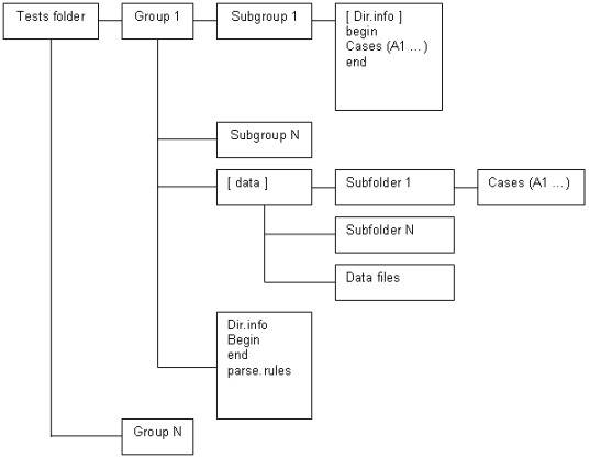
Each test folder is expected to contain:
Each group directory contains:
By convention, names of test groups, grids, and cases should contain no spaces and be lower-case. The names begin, end, data, parse.rules, grids.list and cases.list are reserved.
General layout of test scripts is shown in Figure 1.
The names of directories of test groups containing systematic test grids correspond to the functionality tested by each group.
Example:
Test group bugs is used to collect the tests coming from bug reports. Group demo collects tests of the test system, DRAW, samples, etc.
This test group contains file grids.list, which defines an ordered list of grids in this group in the following format:
Example:
This file is a Tcl script. It is executed before every test in the current group. Usually it loads necessary Draw commands, sets common parameters and defines additional Tcl functions used in test scripts.
Example:
This file is a TCL script. It is executed after every test in the current group. Usually it checks the results of script work, makes a snap-shot of the viewer and writes TEST COMPLETED to the output.
Note: TEST COMPLETED string should be present in the output to indicate that the test is finished without crash.
See Creation and modification of tests chapter for more information.
Example:
The test group may contain parse.rules file. This file defines patterns used for analysis of the test execution log and deciding the status of the test run.
Each line in the file should specify a status (single word), followed by a regular expression delimited by slashes (*/*) that will be matched against lines in the test output log to check if it corresponds to this status.
The regular expressions should follow Tcl syntax, with a special exception that "\b" is considered as word limit (Perl-style), in addition to "\y" used in Tcl.
The rest of the line can contain a comment message, which will be added to the test report when this status is detected.
Example:
Lines starting with a *#* character and blank lines are ignored to allow comments and spacing.
See Interpretation of test results chapter for details.
If a line matches several rules, the first one applies. Rules defined in the grid are checked first, then rules in the group, then rules in the test root directory. This allows defining some rules on the grid level with status IGNORE to ignore messages that would otherwise be treated as errors due to the group level rules.
Example:
The test group may contain subdirectory data, where test scripts shared by different test grids can be put. See also Directory data.
The folder of a test group can have several sub-directories (Grid 1… Grid N) defining test grids. Each directory contains a set of related test cases. The name of a directory should correspond to its contents.
Example:
Here caf is the name of the test group and basic, bugs, presentation, etc. are the names of grids.
This file is a TCL script executed before every test in the current grid.
Usually it sets variables specific for the current grid.
Example:
This file is a TCL script executed after every test in current grid.
Usually it executes a specific sequence of commands common for all tests in the grid.
Example:
The grid directory can contain an optional file cases.list defining an alternative location of the test cases. This file should contain a single line defining the relative path to the collection of test cases.
Example:
This option is used for creation of several grids of tests with the same data files and operations but performed with differing parameters. The common scripts are usually located place in the common subdirectory of the test group, data/simple for example.
If file cases.list exists, the grid directory should not contain any test cases. The specific parameters and pre- and post-processing commands for test execution in this grid should be defined in the files begin and end.
The test grid may contain subdirectory data, containing data files used in tests (BREP, IGES, STEP, etc.) of this grid.
The test case is a TCL script, which performs some operations using DRAW commands and produces meaningful messages that can be used to check the validity of the result.
Example:
The test case can have any name (except for the reserved names begin, end, data, cases.list and parse.rules). For systematic grids it is usually a capital English letter followed by a number.
Example:
Such naming facilitates compact representation of tests execution results in tabular format within HTML reports.
This section describes how to add new tests and update existing ones.
The new tests are usually added in the frame of processing issues in OCCT Mantis tracker. Such tests in general should be added to group bugs, in the grid corresponding to the affected OCCT functionality. See Mapping of OCCT functionality to grid names in group bugs.
New grids can be added as necessary to contain tests for the functionality not yet covered by existing test grids. The test case name in the bugs group should be prefixed by the ID of the corresponding issue in Mantis (without leading zeroes) with prefix bug. It is recommended to add a suffix providing a hint on the tested situation. If more than one test is added for a bug, they should be distinguished by suffixes; either meaningful or just ordinal numbers.
Example:
If the new test corresponds to a functionality already covered by the existing systematic test grid (e.g. group mesh for BRepMesh issues), this test can be added (or moved later by OCC team) to that grid.
It is advisable to make self-contained test scripts whenever possible, so as they could be used in the environments where data files are not available. For that simple geometric objects and shapes can be created using DRAW commands in the test script itself.
If the test requires a data file, it should be put to the directory listed in environment variable CSF_TestDataPath. Alternatively, it can be put to subdirectory data of the test grid. It is recommended to prefix the data file with the corresponding issue id prefixed by bug, e.g. bug12345_face1.brep, to avoid possible conflicts with names of existing data files.
Note that when the test is integrated to the master branch, OCC team will move the data file to the data files repository, to keep OCCT sources repository clean from data files.
When you prepare a test script, try to minimize the size of involved data model. For instance, if the problem detected on a big shape can be reproduced on a single face extracted from that shape, use only that face in the test.
If the test cannot be implemented using available DRAW commands, consider the following possibilities:
Note that a DRAW command is expected to return 0 in case of a normal completion, and 1 (Tcl exception) if it is incorrectly used (e.g. a wrong number of input arguments). Thus if the new command needs to report a test error, this should be done by outputting an appropriate error message rather than by returning a non-zero value. File names must be encoded in the script rather than in the DRAW command and passed to the DRAW command as an argument.
The test should run commands necessary to perform the tested operations, in general assuming a clean DRAW session. The required DRAW modules should be loaded by pload command, if it is not done by begin script. The messages produced by commands in a standard output should include identifiable messages on the discovered problems if any.
Usually the script represents a set of commands that a person would run interactively to perform the operation and see its results, with additional comments to explain what happens.
Example:
Make sure that file parse.rules in the grid or group directory contains a regular expression to catch possible messages indicating the failure of the test.
For instance, for catching errors reported by checkshape command relevant grids define a rule to recognize its report by the word Faulty:
For the messages generated in the script it is recommended to use the word 'Error' in the error message.
Example:
At the end, the test script should output TEST COMPLETED string to mark a successful completion of the script. This is often done by the end script in the grid.
When the test script requires a data file, use Tcl procedure locate_data_file to get a path to it, instead of putting the path explicitly. This will allow easy move of the data file from OCCT sources repository to the data files repository without the need to update the test script.
Example:
When the test needs to produce some snapshots or other artefacts, use Tcl variable imagedir as the location where such files should be put.
However if variable imagedir is defined on the top level of Tcl interpretor, command test will use it instead of creating a new directory.
Use Tcl variable casename to prefix all files produced by the test. This variable is set to the name of the test case.
The test system can recognize an image file (snapshot) and include it in HTML log and differences if its name starts with the name of the test case (use variable casename), optionally followed by underscore or dash and arbitrary suffix.
The image format (defined by extension) should be png.
Example:
would produce:
Note that OCCT must be built with FreeImage support to be able to produce usable images.
Other Tcl variables defined during the test execution are:
In order to ensure that the test works as expected in different environments, observe the following additional rules:
The result of the test is evaluated by checking its output against patterns defined in the files parse.rules of the grid and group.
The OCCT test system recognizes five statuses of the test execution:
Other statuses can be specified in parse.rules files, these will be classified as FAILED.
For integration of the change to OCCT repository, all tests should return either OK or BAD status. The new test created for an unsolved problem should return BAD. The new test created for a fixed problem should return FAILED without the fix, and OK with the fix.
If the test produces an invalid result at a certain moment then the corresponding bug should be created in the OCCT issue tracker located at https://tracker.dev.opencascade.org, and the problem should be marked as TODO in the test script.
The following statement should be added to such a test script:
Here:
Example:
Example:
The parser checks the test output and if an output line matches the RegularExpression then it will be assigned a BAD status instead of FAILED.
A separate TODO line must be added for each output line matching an error expression to mark the test as BAD. If not all TODO messages are found in the test log, the test will be considered as possible improvement.
To mark the test as BAD for an incomplete case (when the final TEST COMPLETE message is missing) the expression TEST INCOMPLETE should be used instead of the regular expression.
Example:
To check the obtained test output matches the expected results considered correct, add REQUIRED statement for each specific message. For that, the following statement should be added to the corresponding test script:
Here ListOfPlatforms and RegularExpression have the same meaning as in TODO statements described above.
The REQUIRED statement can also be used to mask the message that would normally be interpreted as error (according to the rules defined in parse.rules) but should not be considered as such within the current test.
Example:
This statement notifies test system that errors reported by checkshape command are expected in that test case, and test should be considered as OK if this message appears, despite of presence of general rule stating that 'Faulty' signals failure.
If output does not contain required statement, test case will be marked as FAILED.
Sometimes it might be necessary to run tests on the previous versions of OCCT (<= 6.5.4) that do not include this test system. This can be done by adding DRAW configuration file DrawAppliInit in the directory, which is current by the moment of DRAW start-up, to load test commands and to define the necessary environment.
Note: in OCCT 6.5.3, file DrawAppliInit already exists in $CASROOT/src/DrawResources, new commands should be added to this file instead of a new one in the current directory.
For example, let us assume that d:/occt contains an up-to-date version of OCCT sources with tests, and the test data archive is unpacked to d:/test-data):
Note that on older versions of OCCT the tests are run in compatibility mode and thus not all output of the test command can be captured; this can lead to absence of some error messages (can be reported as either a failure or an improvement).
You can extend the test system by adding your own tests. For that it is necessary to add paths to the directory where these tests are located, and one or more additional data directories, to the environment variables CSF_TestScriptsPath and CSF_TestDataPath. The recommended way for doing this is using DRAW configuration file DrawAppliInit located in the directory which is current by the moment of DRAW start-up.
Use Tcl command _path_separator to insert a platform-dependent separator to the path list.
For example:
For better efficiency, on computers with multiple CPUs the tests can be run in parallel mode. This is default behavior for command testgrid : the tests are executed in parallel processes (their number is equal to the number of CPUs available on the system). In order to change this behavior, use option parallel followed by the number of processes to be used (1 or 0 to run sequentially).
Note that the parallel execution is only possible if Tcl extension package Thread is installed. If this package is not available, testgrid command will output a warning message.
Some test results are very dependent on the characteristics of the workstation, where they are performed, and thus cannot be checked by comparison with some predefined values. These results can be checked for non-regression (after a change in OCCT code) by comparing them with the results produced by the version without this change. The most typical case is comparing the result obtained in a branch created for integration of a fix (CR***) with the results obtained on the master branch before that change is made.
OCCT test system provides a dedicated command testdiff for comparing CPU time of execution, memory usage, and images produced by the tests.
Here dir1 and dir2 are directories containing logs of two test runs.
Possible options are:
Example:
Particular tests can generate additional data that need to be compared by testdiff command. For that, for each parameter to be controlled, the test should produce the line containing keyword "COUNTER* followed by arbitrary name of the parameter, then colon and numeric value of the parameter.
Example of test code:
This group allows testing the interaction of OCCT and 3rdparty products.
DRAW module: VISUALIZATION.
| Grid | Commands | Functionality |
|---|---|---|
| export | vexport | export of images to different formats |
| fonts | vtrihedron, vcolorscale, vdrawtext | display of fonts |
This group allows testing blends (fillets) and related operations.
DRAW module: MODELING.
| Grid | Commands | Functionality |
|---|---|---|
| simple | blend | fillets on simple shapes |
| complex | blend | fillets on complex shapes, non-trivial geometry |
| tolblend_simple | tolblend, blend | |
| buildevol | buildevol | |
| tolblend_buildvol | tolblend, buildevol | use of additional command tolblend |
| bfuseblend | bfuseblend | |
| encoderegularity | encoderegularity |
This group allows testing Boolean operations.
DRAW module: MODELING (packages BOPTest and BRepTest).
Grids names are based on name of the command used, with suffixes:
| Grid | Commands | Functionality |
|---|---|---|
| bcommon_2d | bcommon | Common operation (old algorithm), 2d |
| bcommon_complex | bcommon | Common operation (old algorithm), complex shapes |
| bcommon_simple | bcommon | Common operation (old algorithm), simple shapes |
| bcut_2d | bcut | Cut operation (old algorithm), 2d |
| bcut_complex | bcut | Cut operation (old algorithm), complex shapes |
| bcut_simple | bcut | Cut operation (old algorithm), simple shapes |
| bcutblend | bcutblend | |
| bfuse_2d | bfuse | Fuse operation (old algorithm), 2d |
| bfuse_complex | bfuse | Fuse operation (old algorithm), complex shapes |
| bfuse_simple | bfuse | Fuse operation (old algorithm), simple shapes |
| bopcommon_2d | bopcommon | Common operation, 2d |
| bopcommon_complex | bopcommon | Common operation, complex shapes |
| bopcommon_simple | bopcommon | Common operation, simple shapes |
| bopcut_2d | bopcut | Cut operation, 2d |
| bopcut_complex | bopcut | Cut operation, complex shapes |
| bopcut_simple | bopcut | Cut operation, simple shapes |
| bopfuse_2d | bopfuse | Fuse operation, 2d |
| bopfuse_complex | bopfuse | Fuse operation, complex shapes |
| bopfuse_simple | bopfuse | Fuse operation, simple shapes |
| bopsection | bopsection | Section |
| boptuc_2d | boptuc | |
| boptuc_complex | boptuc | |
| boptuc_simple | boptuc | |
| bsection | bsection | Section (old algorithm) |
This group allows testing cases coming from Mantis issues.
The grids are organized following OCCT module and category set for the issue in the Mantis tracker. See Mapping of OCCT functionality to grid names in group bugs chapter for details.
This group allows testing OCAF functionality.
DRAW module: OCAFKERNEL.
| Grid | Commands | Functionality |
|---|---|---|
| basic | Basic attributes | |
| bugs | Saving and restoring of document | |
| driver | OCAF drivers | |
| named_shape | TNaming_NamedShape attribute | |
| presentation | AISPresentation attributes | |
| tree | Tree construction attributes | |
| xlink | XLink attributes |
This group allows testing chamfer operations.
DRAW module: MODELING.
The test grid name is constructed depending on the type of the tested chamfers. Additional suffix _complex is used for test cases involving complex geometry (e.g. intersections of edges forming a chamfer); suffix _sequence is used for grids where chamfers are computed sequentially.
| Grid | Commands | Functionality |
|---|---|---|
| equal_dist | Equal distances from edge | |
| equal_dist_complex | Equal distances from edge, complex shapes | |
| equal_dist_sequence | Equal distances from edge, sequential operations | |
| dist_dist | Two distances from edge | |
| dist_dist_complex | Two distances from edge, complex shapes | |
| dist_dist_sequence | Two distances from edge, sequential operations | |
| dist_angle | Distance from edge and given angle | |
| dist_angle_complex | Distance from edge and given angle | |
| dist_angle_sequence | Distance from edge and given angle |
This group tests reading and writing of CAD data files (iges, step) to and from OCCT.
Test cases check transfer status, shape and attributes against expected reference values.
| Grid | Commands | Functionality |
|---|---|---|
| iges_1, iges_2, iges_3 | igesbrep, brepiges, ReadIges, WriteIges | IGES tests |
| step_1, step_2, step_3, step_4, step_5 | stepread, stepwrite, ReadStep, WriteStep | STEP tests |
This group allows demonstrating how testing cases are created, and testing DRAW commands and the test system as a whole.
| Grid | Commands | Functionality |
|---|---|---|
| draw | getsource, restore | Basic DRAW commands |
| testsystem | Testing system | |
| samples | OCCT samples |
This group allows testing draft operations.
DRAW module: MODELING.
| Grid | Commands | Functionality |
|---|---|---|
| Angle | depouille | Drafts with angle (inclined walls) |
This group allows testing creation of features on a shape.
DRAW module: MODELING (package BRepTest).
| Grid | Commands | Functionality |
|---|---|---|
| featdprism | ||
| featlf | ||
| featprism | ||
| featrevol | ||
| featrf |
This group allows testing the functionality provided by ShapeHealing toolkit.
DRAW module: XSDRAW
| Grid | Commands | Functionality |
|---|---|---|
| fix_shape | fixshape | Shape healing |
| fix_gaps | fixwgaps | Fixing gaps between edges on a wire |
| same_parameter | sameparameter | Fixing non-sameparameter edges |
| same_parameter_locked | sameparameter | Fixing non-sameparameter edges |
| fix_face_size | DT_ApplySeq | Removal of small faces |
| elementary_to_revolution | DT_ApplySeq | Conversion of elementary surfaces to revolution |
| direct_faces | directfaces | Correction of axis of elementary surfaces |
| drop_small_edges | fixsmall | Removal of small edges |
| split_angle | DT_SplitAngle | Splitting periodic surfaces by angle |
| split_angle_advanced | DT_SplitAngle | Splitting periodic surfaces by angle |
| split_angle_standard | DT_SplitAngle | Splitting periodic surfaces by angle |
| split_closed_faces | DT_ClosedSplit | Splitting of closed faces |
| surface_to_bspline | DT_ToBspl | Conversion of surfaces to b-splines |
| surface_to_bezier | DT_ShapeConvert | Conversion of surfaces to bezier |
| split_continuity | DT_ShapeDivide | Split surfaces by continuity criterion |
| split_continuity_advanced | DT_ShapeDivide | Split surfaces by continuity criterion |
| split_continuity_standard | DT_ShapeDivide | Split surfaces by continuity criterion |
| surface_to_revolution_advanced | DT_ShapeConvertRev | Convert elementary surfaces to revolutions, complex cases |
| surface_to_revolution_standard | DT_ShapeConvertRev | Convert elementary surfaces to revolutions, simple cases |
| update_tolerance_locked | updatetolerance | Update the tolerance of shape so that it satisfy the rule: toler(face)<=toler(edge)<=toler(vertex) |
This group allows testing shape tessellation (BRepMesh) and shading.
DRAW modules: MODELING (package MeshTest), VISUALIZATION (package ViewerTest)
| Grid | Commands | Functionality |
|---|---|---|
| advanced_shading | vdisplay | Shading, complex shapes |
| standard_shading | vdisplay | Shading, simple shapes |
| advanced_mesh | mesh | Meshing of complex shapes |
| standard_mesh | mesh | Meshing of simple shapes |
| advanced_incmesh | incmesh | Meshing of complex shapes |
| standard_incmesh | incmesh | Meshing of simple shapes |
| advanced_incmesh_parallel | incmesh | Meshing of complex shapes, parallel mode |
| standard_incmesh_parallel | incmesh | Meshing of simple shapes, parallel mode |
This group allows testing creation of simple surfaces.
DRAW module: MODELING (package BRepTest)
| Grid | Commands | Functionality |
|---|---|---|
| after_trim | mkface | |
| after_offset | mkface | |
| after_extsurf_and_offset | mkface | |
| after_extsurf_and_trim | mkface | |
| after_revsurf_and_offset | mkface | |
| mkplane | mkplane |
This group allows testing normal projection of edges and wires onto a face.
DRAW module: MODELING (package BRepTest)
| Grid | Commands | Functionality |
|---|---|---|
| Base | nproject |
This group allows testing offset functionality for curves and surfaces.
DRAW module: MODELING (package BRepTest)
| Grid | Commands | Functionality |
|---|---|---|
| compshape | offsetcompshape | Offset of shapes with removal of some faces |
| faces_type_a | offsetparameter, offsetload, offsetperform | Offset on a subset of faces with a fillet |
| faces_type_i | offsetparameter, offsetload, offsetperform | Offset on a subset of faces with a sharp edge |
| shape_type_a | offsetparameter, offsetload, offsetperform | Offset on a whole shape with a fillet |
| shape_type_i | offsetparameter, offsetload, offsetperform | Offset on a whole shape with a fillet |
| shape | offsetshape | |
| wire_closed_outside_0_005, wire_closed_outside_0_025, wire_closed_outside_0_075, wire_closed_inside_0_005, wire_closed_inside_0_025, wire_closed_inside_0_075, wire_unclosed_outside_0_005, wire_unclosed_outside_0_025, wire_unclosed_outside_0_075 | mkoffset | 2d offset of closed and unclosed planar wires with different offset step and directions of offset ( inside / outside ) |
This group allows testing construction of pipes (sweeping of a contour along profile).
DRAW module: MODELING (package BRepTest)
| Grid | Commands | Functionality |
|---|---|---|
| Standard | pipe |
This group allows testing construction of prisms.
DRAW module: MODELING (package BRepTest)
| Grid | Commands | Functionality |
|---|---|---|
| seminf | prism |
This group allows testing sewing of faces by connecting edges.
DRAW module: MODELING (package BRepTest)
| Grid | Commands | Functionality |
|---|---|---|
| tol_0_01 | sewing | Sewing faces with tolerance 0.01 |
| tol_1 | sewing | Sewing faces with tolerance 1 |
| tol_100 | sewing | Sewing faces with tolerance 100 |
This group allows testing construction of shell or a solid passing through a set of sections in a given sequence (loft).
| Grid | Commands | Functionality |
|---|---|---|
| solids | thrusection | Lofting with resulting solid |
| not_solids | thrusection | Lofting with resulting shell or face |
This group allows testing extended data exchange packages.
| Grid | Commands | Functionality |
|---|---|---|
| dxc, dxc_add_ACL, dxc_add_CL, igs_to_dxc, igs_add_ACL, brep_to_igs_add_CL, stp_to_dxc, stp_add_ACL, brep_to_stp_add_CL, brep_to_dxc, add_ACL_brep, brep_add_CL | Subgroups are divided by format of source file, by format of result file and by type of document modification. For example, brep_to_igs means that the source shape in brep format was added to the document, which was saved into igs format after that. The postfix add_CL means that colors and layers were initialized in the document before saving and the postfix add_ACL corresponds to the creation of assembly and initialization of colors and layers in a document before saving. |
| OCCT Module / Mantis category | Toolkits | Test grid in group bugs |
|---|---|---|
| Application Framework | PTKernel, TKPShape, TKCDF, TKLCAF, TKCAF, TKBinL, TKXmlL, TKShapeSchema, TKPLCAF, TKBin, TKXml, TKPCAF, FWOSPlugin, TKStdLSchema, TKStdSchema, TKTObj, TKBinTObj, TKXmlTObj | caf |
| Draw | TKDraw, TKTopTest, TKViewerTest, TKXSDRAW, TKDCAF, TKXDEDRAW, TKTObjDRAW, TKQADraw, DRAWEXE, Problems of testing system | draw |
| Shape Healing | TKShHealing | heal |
| Mesh | TKMesh, TKXMesh | mesh |
| Data Exchange | TKIGES | iges |
| Data Exchange | TKSTEPBase, TKSTEPAttr, TKSTEP209, TKSTEP | step |
| Data Exchange | TKSTL, TKVRML | stlvrml |
| Data Exchange | TKXSBase, TKXCAF, TKXCAFSchema, TKXDEIGES, TKXDESTEP, TKXmlXCAF, TKBinXCAF | xde |
| Foundation Classes | TKernel, TKMath | fclasses |
| Modeling_algorithms | TKGeomAlgo, TKTopAlgo, TKPrim, TKBO, TKBool, TKHLR, TKFillet, TKOffset, TKFeat, TKXMesh | modalg |
| Modeling Data | TKG2d, TKG3d, TKGeomBase, TKBRep | moddata |
| Visualization | TKService, TKV2d, TKV3d, TKOpenGl, TKMeshVS, TKNIS | vis |
Run command checkshape on the result (or intermediate) shape and make sure that parse.rules of the test grid or group reports bad shapes (usually recognized by word "Faulty") as error.
Example
To check the number of faults in the shape command checkfaults can be used.
Use: checkfaults shape source_shape [ref_value=0]
The default syntax of checkfaults command:
The command will check the number of faults in the source shape (a_1) and compare it with number of faults in the resulting shape (result). If shape result contains more faults, you will get an error:
It is possible to set the reference value for comparison (reference value is 4):
If number of faults in the resulting shape is unstable, reference value should be set to "-1". As a result command checkfaults will return the following error:
The maximal tolerance of sub-shapes of each kind of the resulting shape can be extracted from output of tolerance command as follows:
It is possible to use command checkmaxtol to check maximal tolerance of shape and compare it with reference value.
Use: checkmaxtol shape [options...]
Allowed options are:
The default syntax of checkmaxtol command for comparison with the reference value:
There is an opportunity to compare max tolerance of resulting shape with max tolerance of source shape. In the following example command checkmaxtol gets max tolerance among objects a_1 and a_2. Then it chooses the maximum value between founded tolerance and value -min_tol (0.000001) and multiply it on the coefficient -multi_tol (i.e. 2):
If the value of maximum tolerance more than founded tolerance for comparison, the command will return an error.
Also, command checkmaxtol can be used to get max tolerance of the shape:
Use command vprops, sprops, or lprops to correspondingly measure volume, area, or length of the shape produced by the test. The value can be extracted from the result of the command by regexp.
Example:
The test system measures the amount of memory used by each test case. Considerable deviations (as well as the overall difference) in comparison with reference results can be reported by command testdiff (see Checking non-regression of performance, memory, and visualization).
To check memory leak on a particular operation, run it in a cycle, measure the memory consumption at each step and compare it with a threshold value. The command checktrend (defined in tests/bugs/begin) can be used to analyze a sequence of memory measurements and to get a statistically based evaluation of the leak presence.
Example:
The following command sequence allows you to take a snapshot of the viewer, give it the name of the test case, and save in the directory indicated by Tcl variable imagedir.
This image will be included in the HTML log produced by testgrid command and will be checked for non-regression through comparison of images by command testdiff.
Also it is possible to use command checkview to make a snapshot of the viewer.
Use: checkview [options...] Allowed options are:
Note that is required to use either option -2d or option -3d.
Examples:
Procedure checkfreebounds compares the number of free edges with a reference value.
Use: checkfreebounds shape ref_value [options...]
Allowed options are:
Option -tol N defines tolerance for command freebounds, which is used within command checkfreebounds.
Option -type N is used to select the type of counted free edges: closed or open.
If the number of free edges in the resulting shape is unstable, the reference value should be set to "-1". As a result command checkfreebounds will return the following error:
Procedure checkreal checks the equality of two reals with a tolerance (relative and absolute).
Use: checkreal name value expected tol_abs tol_rel
Procedure checknbshapes compares the number of sub-shapes in "shape" with the given reference data.
Use: checknbshapes shape [options...]
Allowed options are:
Command checkcolor can be used to check pixel color.
Use: checkcolor x y red green blue
where:
This procedure checks color with tolerance (5x5 area).
Next example will compare color of point with coordinates x=100 y=100 with RGB color R=1 G=0 B=0. If colors are not equal, procedure will check the nearest ones points (5x5 area)
Procedure checkprops computes length, area and volume of the input shape.
Use: checkprops shapename [options...]
Allowed options are:
Options -l, -s and -v are independent and can be used in any order. Tolerance epsilon is the same for all options.
Procedure checkdump is used to parse output dump and compare it with reference values.
Use: checkdump shapename [options...]
Allowed options are:
Procedure checklength computes length of the input curve.
Use: checklength curvename [options...]
Allowed options are:
Command checktrinfo can be used to to check the maximum deflection, as well as the number of nodes and triangles in mesh.
Use: checktrinfo shapename [options...]
Allowed options are:
Note that options -tri, -nod and -defl do not work together with option -ref.
Examples:
Comparison with some reference values:
Comparison with another mesh:
Comparison of deflection with the max possible value:
Check that the current values are not equal to zero:
Check that the number of triangles and the number of nodes are not equal to some specific values:
It is possible to compare current values with reference values with some tolerances. Use options -tol_* for that.
 1.8.13